|
Free
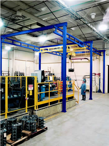
Standing Work Station
Bridge Cranes
|
|
|
|
|
|
| |
| |
|
|
|
|
|
The safe, productive,
ergonomic solution for
overhead materials handling operations.
|
|
Enclosed
Track Design Makes for Easy
Movement and Long Life |
|
|
|
|
|
|
|
|
 |
|
The steel Work
Station Crane System utilize enclosed
track that is high in strength and low in weight. Major
advantages:
• Enclosed track cranes are up to three times easier to
move than traditional bridge cranes.
• The design virtually eliminates dirt and dust from the
rolling surface, thus reducing wear on the wheels of
the trolley and end trucks.
• The smooth running surface means lower rolling
resistance.
• The low profile of the steel track allows the system
to be installed where headroom is a problem.
• The low track weight reduces the applied forces
exerted on the supporting structure.
• Long spans allow systems to be installed where
support assemblies are infrequent (up to 30 feet with
steel truss design). This reduces the possibility of the
support columns interfering with the work cell layout.
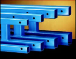
• Four distinct sizes of track -- 250, 500, 1000, and
2000 series -- enable you to keep bridge weights
and costs to a minimum. |
|
|
|
|
|
Pricing
and Dimensional Specifications -
Click a Load Capacity Link Here |
|
|
|
|
|
|
|
|
|
|
|
|
|
| |
|
|
|
|
|
|
|
|
|
|
|
|
|
|
Rigid
Runways Provide for Superior
Positioning of Loads |
|
|
|
|
|
|
|
|
|
|
 |
|
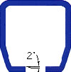
The
2° taper of the running
flange helps to center the
trolley in the track for smooth,
effortless movement of trolleys
and end trucks. |
|
|
Work Station Bridge Cranes
are installed so that the
runways are rigid. They do not move laterally or
longitudinally. In addition, the floating end trucks with
horizontal wheels prevent binding. The combination of
these design features results in unmatched ease of
positioning and ease of movement. The bridge travels
smoothly down the runways, and movement is unvarying
along the way, no matter where a load is positioned on
the bridge. This allows superior load positioning.
Another advantage of rigid runways is that runways
double as stringers between support columns. This
eliminates the need for expensive intermediate support
stringers, and it lowers overall installation cost.
|
|
|
|
|
|
|
|
|
|
|
|
|
|
|
|
 |
|
|
|
|
|
|
|
|
| What
is meant by Rated Capacity? |
|
|
|
|
|
|
|
|
|
|
|
|
|
The
rated capacity is the live load that can be lifted by
the crane system. The design load for the crane system
is based on the rated capacity plus 15% for the weight
of the hoist and trolley (capacity x 1.15) and an additional
25% for impact (capacity x 1.25) for a total design of
capacity x 1.4 (Note, 25% impact factor is good for
hoist speeds up to 50 f.p.m.). For example, a 1000 lb.
crane allows you to pick up a 1000 lbs. load, provided
the hoist weights 150 lbs. or less and the hoist speed is
less than 50 feet per minute. |
TRUSSED
STEEL TRACK: |
|
|
|
|
|
|
|
|
Permits
longer spans which allows more flexibility
in crane layout. |
|
|
|
|
|
|
|
|
|
The trussed series uses the
plain steel track profile but is
enhanced for longer spans via a built-up truss design. This
design increases the span, which decreases the need for
frequent hangers. Model numbers start with: GLCS-FS
for spans up to 20 feet, GLCSL-FS for spans up to 25
feet, and GLCSLX-FS for spans up to 30 feet.
Long spans translate into fewer runway support points,
less interference of work cell layout, longer bridge lengths,
and free standing capabilities... just another reason why
these Work Station Cranes are among the most versatile
to apply and easiest to install in the industry.
|
|
|
|
|
Design
load for deflection calculations is based on
the rated capacity plus 15% for the weight of the hoist
and trolley (capacity x 1.15). Under no conditions should
the crane be loaded beyond it rated capacity. Work
Station Cranes meet or exceed the ANSI B30.11
specifications for underhung bridge cranes. |
|
|
|
|
|
|
|
|
|
|
|
| |
|
|
|
|
|
|
|
|
|
|
|
|
|
|
| Mixed
Capacity Bridge Crane Systems: |
|
Easy
to Install |
|
|
|
|
Reduced
bridge dead weight equals better ergonomic
solutions. |
|
Free
Standing Work Station Bridge Cranes can be
installed on any normal 6" reinforced concrete floor.
Each column is anchored by four bolts, thus eliminating
the need for field welding.
Support columns are designed to AISC specifications. If
no movement of the support assemblies is required, then
bracing to the building is recommended (not included). |
|
|
Mixed-capacity
systems allow multiple lower capacity
bridges to be used on higher capacity runways, provided
the equivalent center loads (ECL) are verified at the
factory to ensure that runways and hangers are not
overloaded. For example, using mixed-capacity end
trucks, four 500 lb. bridges (utilizing 500 series rail)
can be hung from a 2000 lb. runway, allowing side-by-
side use of all four bridges without overloading the
system. By mixing bridges of various sizes and cap-
acities, mixed-capacity systems offer reduced bridge
dead weight, easier movement, and reduced cost. |
|
|
|
|
|
Modular
Design |
|
The
pre-engineered modular kit design permits easy
expansion or relocation. The runway length can be
increased by adding runway sections, free standing
support assemblies and additional bridges as needed. |
|
|
|
|
Pricing
and Dimensional Specifications -
Click a Load Capacity Link Here > |
|
|
|
|
|
|
|
|
|
|
|
|
|
|
|
|
|
|
CAPACITY |
SERIES |
WEIGHT
PER
FOOT |
MAX.
L1 |
MAX.
L2 |
MAX.
L5 |
MAX.
L9 |
| 250# |
GLCS |
4.88# |
20' |
48" |
18’’ |
48’’ |
|
GLCSL |
8.14# |
25' |
48" |
18’’ |
48’’ |
| 500# |
GLCS |
7.23# |
20' |
48" |
18’’ |
48’’ |
|
GLCSL |
10.94# |
25' |
48" |
24’’ |
48’’ |
|
GLCSLX |
11.26# |
30' |
48" |
24’’ |
48’’ |
| 1000# |
GLCS |
12.09# |
20' |
48" |
24’’ |
48’’ |
|
GLCSL |
13.37# |
25' |
48" |
24’’ |
48’’ |
|
GLCSLX |
15.31# |
30' |
48" |
24’’ |
48’’ |
| 2000# |
GLCS |
14.59# |
20' |
48" |
24’’ |
48’’ |
|
GLCSL |
20.14# |
25' |
48" |
24’’ |
48’’ |
|
GLCSLX |
20.95# |
30' |
48" |
24’’ |
48’’ |
| 4000# |
GLCS |
18.42# |
20' |
48" |
24’’ |
48’’ |
|
GLCSL |
23.83# |
25' |
48" |
24’’ |
48’’ |
|
GLCSLX |
28.02# |
30' |
48" |
24’’ |
48’’ |
|
|
 |
|
|
|
|
|
|
|
|
|
|
|
|
|
|
|
|
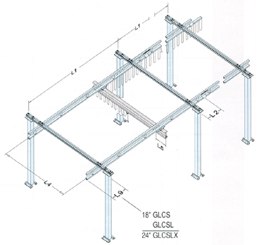
L
1 = |
MAXIMUM
SUPPORT ASSEMBLY CENTERLINE
Maximum Support Assembly Centerline is con-
sidered from the center of a support assembly to
the center of the neighboring support assembly. |
|
|
|
|
|
|
| Note: |
Anti-kick-up
end trucks* are required for the following:
bridges with < 8' span (L4) and a bridge
cantilever (L5) > 12"
bridges with < 10' span (L4) and a bridge
cantilever (L5) > 15"
bridges with < 15' span (L4) and a bridge
cantilever (L5) > 18" |
|
|
|
|
|
|
|
L
2 = |
SPLICE
JOINT CENTERLINE TO SUP-
PORT ASSEMBLY CENTERLINE
Splice Joint Centerline to Support Assembly Cen-
terline is considered from center of a splice joint
to the center of the nearest support assembly. |
|
|
|
|
|
**
|
|
|
|
|
|
|
|
|
|
|
|
|
|
|
L
4 = |
BRIDGE SPAN
Bridge Span is considered from centerline to cen-
terline of runways.
L4 = Bridge Overall Length - (2 x Bridge Centerline)
|
|
|
|
|
|
|
|
|
|
|
*
Anti-kick-up end trucks are not included as part
of the standard crane kits.
**2000# @ 10' span (L4) and bridge cantilever (L5)
15" need anti-kick-up end trucks.
Consult us for information on bridges greater
than 15' span (L4). |
|
|
|
|
|
| L
5 = |
BRIDGE
CANTILEVER
Bridge Cantilever is considered from the center-
line of the runway to the end of the bridge (see
table and notes). |
|
|
|
|
|
|
|
|
|
STANDARD BRIDGE CANTILEVER
|
Bridge
Series |
Bridge Overall Length |
|
Steel |
|
<=23' |
28' |
29' |
33' |
34' |
| 250# |
12" |
18" |
24" |
NA |
NA |
| 500# |
12" |
18" |
24" |
18" |
24" |
| 1000# |
12" |
18" |
24" |
18" |
24" |
| 2000# |
12" |
18" |
24" |
18" |
24" |
| 4000# |
15" |
18" |
24" |
18" |
24" |
|
|
|
|
|
|
L
9 = |
MAXIMUM
RUNWAY CANTILEVER
Runway Cantilever is considered from the center
of the end support assembly to the end of the
runway. |
|
|
|
|
|
|
|


